
Model 21 Cap Circular Flange Mount
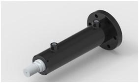
These mounts are ideal for straight line force transfer applications in which the cylinder is used in tension (pulling). The mounting surface should be flat, and the rod end cartridge should be piloted into it. The frame on which the cylinder is mounted must be sufficiently rigid to resist bending moments. The force of the load should be perpendicular to the mounting surface and parallel to the centerline of the piston rod. For eccentric loads, the larger of the two available rods in each bore size is recommended. Stop tubes should also be considered.
Enquiry Now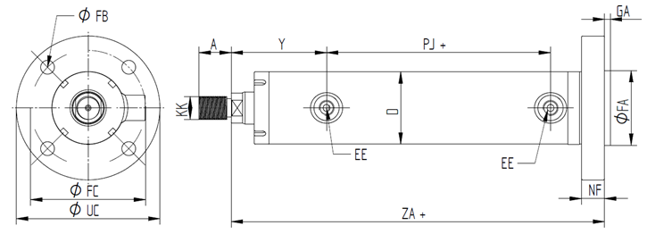
| Bore | Rod | KK | A | UC | NF | FC | FA | GA | FB | Y | EE | D | PJ | ZA |
|---|---|---|---|---|---|---|---|---|---|---|---|---|---|---|
| 50 | 28 | M20 x 1.5 | 28 | 125 | 20 | 100 | 65 | 5 | Ø12 X 4 | 83 | 1/4" BSP | 63 | 45 | 175 |
| 36 | M27 x 2 | 36 | ||||||||||||
| 63 | 36 | M27 x 2 | 36 | 145 | 20 | 115 | 75 | 5 | Ø14 X 4 | 83 | 3/8" BSP | 76 | 45 | 175 |
| 45 | M33 x 2 | 45 | ||||||||||||
| 80 | 45 | M33 x 2 | 45 | 180 | 25 | 150 | 90 | 5 | Ø18 X 4 | 90 | 1/2" BSP | 100 | 58 | 212 |
| 56 | M42 x 2 | 56 | ||||||||||||
| 100 | 56 | M42 x 2 | 56 | 205 | 30 | 175 | 115 | 5 | Ø18 X 6 | 100 | 1/2" BSP | 125 | 73 | 242 |
| 70 | M48 x 2 | 63 | ||||||||||||
| 125 | 70 | M48 x 2 | 63 | 240 | 32 | 205 | 125 | 5 | Ø18 X 6 | 120 | 3/4" BSP | 150 | 90 | 289 |
| 90 | M80 x 3 | 95 |