
Model 29: Head Circular Flange Mount
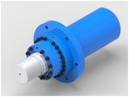
The flange mount is one of the strongest, most rigid methods of mounting. These cylinders are also suitable for use on straight line force transfer applications. With this type of mount, there is little allowance for misalignment. When long strokes are required, the free end opposite the mounting should be supported to prevent sagging and possible binding of the cylinder.
Enquiry Now


| Bore | Rod | KK | A | FA | GA | UC | NF | FC | FB | IS | OH | VE | WF | Y | EE | EE" | D | ZJ |
|---|---|---|---|---|---|---|---|---|---|---|---|---|---|---|---|---|---|---|
| 100 | 56 | M42 x 2 | 56 | 135 | 5 | 240 | 30 | 210 | Ø18 X 6 | 231 | 175 | 40 | 145 | 125 | 1/2" BSP | 1/2" BSP | 125 | 275 |
| 70 | M48 x 2 | 63 | 238 | |||||||||||||||
| 125 | 70 | M48 x 2 | 63 | 160 | 5 | 275 | 32 | 235 | Ø18 X 6 | 250 | 200 | 50 | 155 | 130 | 3/4" BSP | 3/4" BSP | 150 | 310 |
| 90 | M80 x 3 | 95 | 282 | |||||||||||||||
| 140 | 90 | M80 x 3 | 95 | 180 | 5 | 290 | 32 | 255 | Ø18 X 6 | 282 | 220 | 95 | 155 | 130 | 1" BSP | 3/4" BSP | 170 | 350 |
| 110 | M80 x 3 | |||||||||||||||||
| 160 | 110 | 80 x 3 | 95 | 210 | 5 | 310 | 38 | 280 | Ø18 X 6 | 298 | 245 | 50 | 165 | 140 | 1" BSP | 3/4" BSP | 195 | 365 |
| 125 | 115 x 3 | 110 | 313 | |||||||||||||||
| 180 | 110 | 80 x 3 | 95 | 235 | 5 | 295 | 42 | 260 | Ø18 X 6 | 297 | 225 | 50 | 160 | 135 | 1" BSP | 3/4" BSP | 225 | 360 |
| 125 | 115 x 3 | 110 | 335 | 305 | 317 | 270 | 165 | 140 | 365 | |||||||||
| 200 | 125 | 115 x 3 | 110 | 260 | 5 | 310 | 42 | 280 | Ø18 X 6 | 317 | 245 | 50 | 165 | 140 | 1" BSP | 3/4" BSP" | 240 | 365 |
| 140 | 125 x 4 | 125 | 340 | 310 | 332 | 275 | ||||||||||||
| 225 | 140 | 125 x 4 | 125 | 290 | 5 | 375 | 55 | 325 | Ø22 X 8 | 345 | 275 | 50 | 165 | 140 | 1" BSP | 3/4" BSP | 270 | 380 |
| 160 | 420 | 370 | 355 | 320 | 175 | 150 | 390 | |||||||||||
| 250 | 140 | 125 x 4 | 125 | 320 | 5 | 400 | 55 | 355 | Ø22 X 8 | 362 | 300 | 50 | 182 | 157 | 1" BSP | 3/4" BSP | 300 | 402 |
| 160 | ||||||||||||||||||
| 180 | ||||||||||||||||||
| 300 | 160 | 125 x 4 | 125 | 370 | 5 | 450 | 60 | 400 | Ø22 X 8 | 372 | 350 | 55 | 187 | 159.5 | 1-1/2" BSP | 1" BSP | 350 | 437 |
| 180 | ||||||||||||||||||
| 320 | 160 | 125 x 4 | 125 | 390 | 5 | 470 | 60 | 420 | Ø22 X 8 | 372 | 370 | 55 | 187 | 159.5 | 1-1/2" BSP | 1" BSP | 370 | 437 |
| 180 |